How to Choose a Bolted Crane Rail Clip in 2026?
Choosing a Bolted Crane Rail Clip in 2026 requires more than comparing prices, thread sizes, or catalog photographs. The connection must match rail profile, wheel loading, runway alignment, impact forces, and maintenance access. Reports from Grand View Research and Research and Markets continue to link crane-market growth with heavier industrial handling and modernized facilities. That trend increases the importance of verified rail restraint, not merely stronger-looking hardware.
CMAA Specification No. 70, EN 15011, ISO 9927-1, and FEM guidance provide useful technical references. They do not replace project calculations. A clip that fits a 60-kilogram rail may still perform poorly under repeated lateral movement. Check bolt grade, tightening method, washer arrangement, corrosion protection, and rail expansion gaps. Site experience matters here. Dust can hide loosening. Paint can obstruct inspection. A small misalignment can become visible as flange wear.
Dr. John W. Fisher, a respected steel-connection researcher, offered a principle that applies well: “Connections deserve the same attention as the members they join.” That sentence is not a complete selection method. It is a useful warning. In practice, engineers should request tested load data, installation tolerances, fatigue information, and traceable manufacturing records. The 2024 Global Crane Market analyses describe reliability and safety as major purchasing factors, but market summaries rarely show clip-level performance. That gap deserves reflection. This guide explains how to compare a Bolted Crane Rail Clip using evidence, field conditions, and lifecycle risk, while acknowledging that no universal clip suits every runway.
What Is a Bolted Crane Rail Clip and How Does It Work?
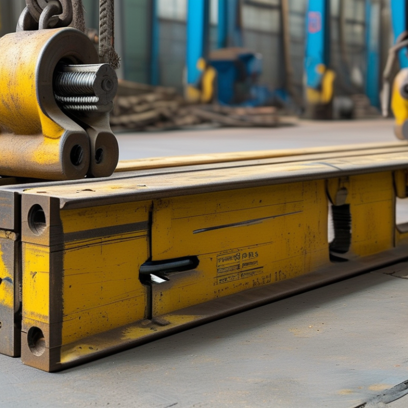
A bolted crane rail clip is a mechanical fastening device that holds a crane rail against its supporting beam. It uses a clip body, bolt, nut, and sometimes a washer or spring element. The rail stays aligned while the crane wheel loads move across it. Simple in appearance, but not simple in service.
During installation, the bolt applies clamping force between the clip and the rail flange. This force limits sideways movement and reduces lifting or vibration. Some clip designs allow controlled rail expansion. That matters when steel temperature changes throughout the day. The connection should remain firm, not brutally tight. Excessive tightening can damage the rail edge or distort the supporting structure.
Choosing the right clip begins with the rail profile, flange thickness, wheel load, and operating frequency. Check the manufacturer’s tested load data, bolt grade, tightening method, and corrosion protection. Field experience also shows that fit matters more than appearance. A clip may look strong but fail to seat evenly on a dirty beam. Clean contact surfaces and use calibrated tools. Inspect loose nuts, cracked clips, rust, and rail movement during scheduled maintenance. Do not rely only on visual checks; a torque reading can reveal trouble earlier. I have seen installation plans overlook drainage and access for future tightening. That small mistake becomes expensive. The safest choice combines verified calculations, competent installation, and a maintenance plan suited to the actual crane environment.
Which Crane Rail Clip Specifications Match Your Rail System?
How to Choose a Bolted Crane Rail Clip in 2026?
Which crane rail clip specifications match your rail system? Start with the rail drawing, not the clip catalogue. Record the rail profile, head width, foot width, rail height, foot thickness, and hole arrangement. DIN 536-1 tables report A45 rail at 22.1 kg/m and A100 rail at 74.3 kg/m. That difference changes clamp reach, bolt loading, and base-plate stiffness. A visually similar clip may still leave an unsafe gap. Measure twice.
Match the clip’s throat opening and contact surfaces to the actual rail foot. Then calculate vertical wheel loads, transverse forces, acceleration, and fatigue cycles. ISO 4301-1 classifies crane service from A1 to A8, reflecting different load spectra and operating intensity. EN 13001 requires crane structures to consider strength, stability, and fatigue. A clip rated only by static capacity is incomplete. It may fail during repeated movement.
Specify bolt diameter, grade, washer size, tightening torque, and available adjustment travel. Check whether the base plate tolerates the required edge distance. For outdoor tracks, corrosion protection should reflect the exposure category described in ISO 12944. Coastal moisture can attack threads first. I have seen installation drawings omit rail misalignment limits, which creates avoidable site disputes. That weakness deserves attention. Ask for tested slip resistance, fatigue evidence, and torque-retention data. Also verify clearance for inspection tools, because a clip that cannot be serviced becomes a hidden maintenance problem.
How to Choose a Bolted Crane Rail Clip in 2026? - Which Crane Rail Clip Specifications Match Your Rail System?
Preliminary dimensional matching guide for bolted crane rail clips. Confirm the actual rail drawing, clip load rating, fastener grade, and installation torque before procurement.
| Reference Rail Profile |
Nominal Rail Height
(mm) |
Nominal Rail Base Width
(mm) |
Nominal Rail Head Width
(mm) |
Recommended Minimum Clip Jaw Opening
(mm) |
Typical Bolt Diameter |
Typical Clip Arrangement |
Primary Verification Point |
| DIN 536 A45 |
55 |
125 |
70 |
75–80 |
M16 |
Two side clips per rail seat |
Check that the clip jaw clears the rail head radius without touching the running surface. |
| DIN 536 A55 |
65 |
150 |
85 |
90–95 |
M16 or M20 |
Two side clips per rail seat |
Verify the available bolt-hole clearance and the clip’s lateral adjustment range. |
| DIN 536 A65 |
75 |
175 |
100 |
105–110 |
M20 |
Two side clips per rail seat |
Confirm that the clip bears on the rail side below the head and does not obstruct wheel travel. |
| DIN 536 A75 |
85 |
200 |
110 |
115–120 |
M20 or M24 |
Two side clips per rail seat |
Check rail alignment tolerance, washer diameter, and the structural capacity of the supporting beam. |
| DIN 536 A100 |
95 |
200 |
150 |
155–160 |
M24 |
Heavy-duty paired clips |
Use the clip manufacturer’s load data for horizontal forces, braking forces, and uplift resistance. |
| DIN 536 A120 |
105 |
220 |
170 |
175–180 |
M24 or M27 |
Heavy-duty paired clips |
Verify bolt pretension, clip stiffness, rail expansion allowance, and fatigue performance. |
Selection rule: Measure the installed rail rather than relying only on the profile name. The clip jaw opening should normally exceed the measured rail head width by approximately 3–8 mm while maintaining positive side contact below the rail head. Bolt diameter, clip spacing, preload, and torque must be checked against the calculated wheel load, lateral force, braking force, uplift, fatigue duty, and the supporting structure.
Important: The dimensions above are nominal reference values for initial screening. Rail tolerances, coatings, welds, rail pads, clip geometry, fastener grade, and installation conditions can change the final specification. Do not select a clip solely by bolt size.
How to Evaluate Load Capacity, Materials, and Operating Conditions
How to Choose a Bolted Crane Rail Clip in 2026?
Selecting a bolted crane rail clip starts with the actual rail load, not the catalogue image. Calculate wheel loads, lateral forces, braking effects, and impact from uneven travel. Include dynamic factors specified by the crane designer. A clip rated only for vertical force may fail during side loading. Check bolt preload, hole spacing, and rail movement limits together. They work as one system.
Material choice depends on the operating environment. High-strength steel suits heavy industrial service, but strength alone is not enough. Look for controlled hardness, fatigue resistance, and reliable coating quality. In coastal yards, salt can attack bolts and contact surfaces quickly. Hot, dusty workshops create different problems. Choose corrosion protection that matches cleaning chemicals, humidity, and maintenance access. Small details matter.
Inspect the rail seat before installation. A bent support or weld spatter can create uneven pressure under the clip. Measure alignment with practical tools, then verify torque using a calibrated wrench. Do not rely on hand-tightened bolts. Thermal expansion also deserves attention, especially on long rails exposed to sunlight. Field conditions rarely match drawings perfectly. No calculation is perfect. Leave room for inspection findings, installation errors, and future wear. A qualified engineer should confirm the final selection against the crane duty cycle and applicable safety requirements.
How to Inspect, Maintain, and Replace Bolted Crane Rail Clips
Choosing a bolted crane rail clip in 2026 requires more than checking its size.
Inspect the rail profile, clip material, bolt grade, and expected wheel loads. The assembly must match the rail system and the crane’s operating conditions. Always verify torque values against approved technical documentation and applicable safety standards.
Guesswork has no place here.
During inspection, look for cracked clips, elongated bolt holes, rust beneath washers, and polished marks along the rail flange.
These marks may show rail movement. Use a calibrated torque wrench, not a spanner held by habit. Check bolt tension at scheduled intervals, especially after installation, heavy lifting, or vibration. Keep the rail seat clean and remove packed dust or metal fragments. Small debris can create uneven contact. It is easy to trust a clean appearance.
That assumption deserves questioning.
Replace a clip when it is cracked, permanently deformed, deeply corroded, or unable to maintain torque.
Replace damaged bolts and locking components together when the system requires it. Never mix unverified parts with an engineered assembly. Isolate the crane, control stored energy, and use competent personnel during replacement. Record the clip location, inspection date, torque result, and observed damage. Photographs help track gradual changes.
Records are often incomplete, unfortunately.
A simple inspection sheet can prevent that weakness. After replacement, confirm rail alignment, fastener seating, and clearance before returning the crane to service.