Leave Your Message

What Are the Top Pipe Support Base Plate Types in 2026?

Pipe Support Base Plate selection can look straightforward until loads, movement, site conditions, and installation access enter the picture. In 2026, buyers may compare flat plates, slotted plates, gusseted designs, adjustable bases, and anchor plates. Each serves different support needs. Details matter.

A flat plate may suit a simple bearing point, while slots can help align supports when bolt positioning needs flexibility. Gussets can add stiffness, but extra steel may affect clearance, weight, fabrication, and corrosion protection. The right choice depends on pipe diameter, operating load, support spacing, base material, and the condition of the concrete or steel below. Designers also consider thermal movement, vibration, anchor layout, drainage, and installation adjustments. Those details are easy to miss on a drawing.

Check project calculations and specifications; appearance alone does not prove capacity. For outdoor or corrosive locations, coating, water traps, and maintenance access deserve attention. Small gaps can collect water. An oversized plate may seem safer, yet it can conflict with nearby steelwork or add unnecessary fabrication. No plate fits all. This guide compares common types, outlines their practical trade-offs, and identifies details worth checking before specification. Where project information is incomplete, pause and verify assumptions with a qualified engineer. That judgment matters.
What Are the Top Pipe Support Base Plate Types in 2026?

Classify 2026 Pipe Support Base Plates by Load Path and Adjustment Method

What Are the Top Pipe Support Base Plate Types in 2026?
Classify 2026 Pipe Support Base Plates by Load Path and Adjustment Method

Pipe support base plates are easier to select when classified by how they transfer loads. A fixed, anchored plate carries vertical loads and may resist lateral forces through its anchors and supporting structure. A bearing plate mainly transfers compression; separate restraints may be needed to control movement. For lines that expand with temperature, sliding plates allow planned travel, while guides limit sideways movement. The details matter.

A second classification is adjustment method. Fixed-height plates suit stable layouts with verified elevations. Shim-adjustable plates use steel shims to correct small site-level differences. Slotted holes or leveling screws offer more positioning range, but must be checked for load, vibration, and locking requirements. A neat drawing can still hide a poor fit: field tolerances and thermal movement sometimes reveal what the model missed. There is no universally best type; the load path, movement allowance, and supporting structure must agree.

Tips: Check anchor layout, plate thickness, and expected travel against the design loads. Keep shim stacks controlled and fully supported. If dimensions or loads are uncertain, confirm them with the project engineer before fabrication.
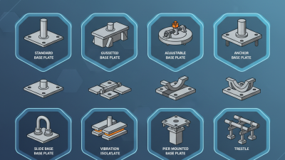
Top Pipe Support Base Plate Types in 2026

Classification by load path and adjustment method

Each bar is a classification flag: 1 means the feature is typical of that plate type; 0 means it is not typical. All types transfer compressive load through bearing. Anchors may also resist uplift or shear when included in the design. Slotted holes generally allow installation positioning before tightening, while shims and leveling screws provide elevation adjustment. Sliding plates allow horizontal movement for thermal travel. Flags are descriptive, not load-capacity ratings.

Compare Flat, Gusseted, Slotted, and Adjustable Plates by Function

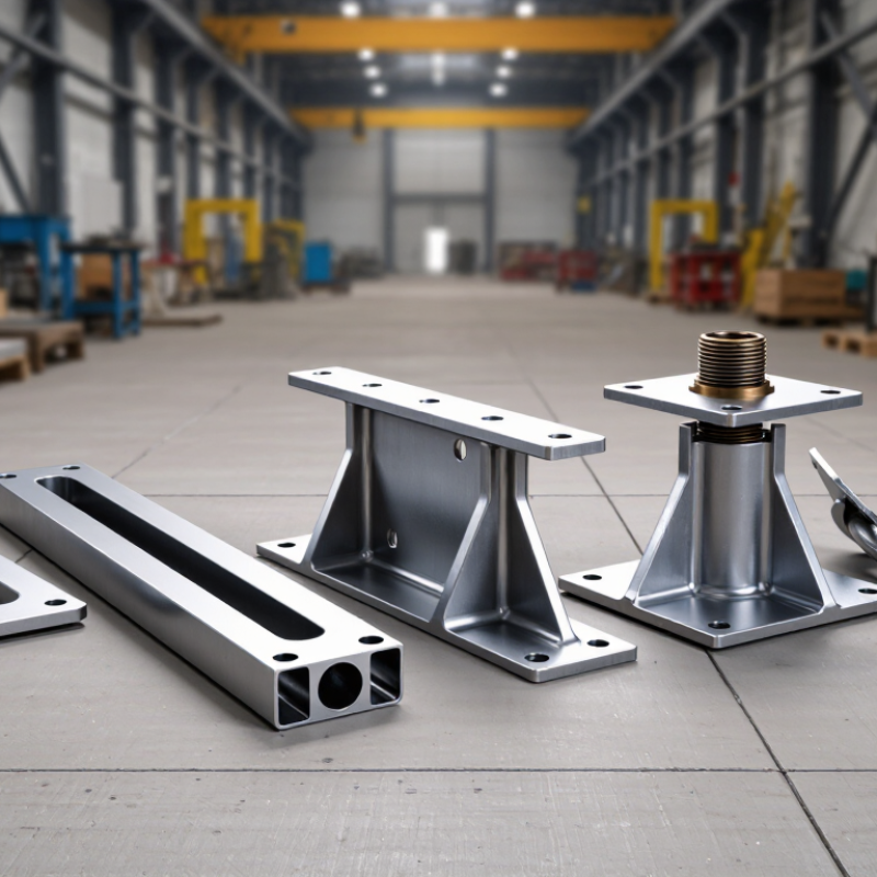
Flat, gusseted, slotted, and adjustable base plates solve different support problems. Flat plates suit light, centered loads on level foundations. Gusseted plates add stiffness where pipe shoes impose higher forces or create an overturning moment. Slotted plates allow limited alignment during installation, but the bolt position must still be checked after tightening. Adjustable plates help level supports on uneven steelwork or accommodate specified height changes. MSS SP-58-2018 provides industry guidance for pipe-support design, selection, and installation; actual load capacity depends on plate dimensions, welds, anchors, and the supporting structure.

Movement matters, too. Using a typical carbon-steel thermal expansion coefficient of about 12 × 10−6 per °C, a 10-meter pipe run changes length by roughly 2.4 millimeters over a 20°C temperature change. That is an estimate, not a design allowance. ASME B31.3-2022 addresses piping flexibility and displacement effects, so confirm movement and loads against the project design basis. A slot can look forgiving on paper; in the field, poor alignment or anchor placement can still bind the support.

Tips: Match the plate to load and movement, not appearance. Check the support drawing, base dimensions, anchor layout, and site level before fabrication. Recheck after installation. Small mismatches matter.

Choose Plate Steel: ASTM A36 (36 ksi) or A572 Grade 50 (50 ksi)

A pipe support base plate must spread load into the foundation without excessive bending around the pipe shoe or anchor bolts. ASTM A36 has a minimum yield strength of 36 ksi and is often a practical choice for moderate loads, standard plate thicknesses, and straightforward fabrication. A572 Grade 50 provides a 50 ksi minimum yield strength, which can help where loads are higher or plate dimensions are constrained. Stronger does not automatically mean thinner. Plate stiffness, bolt spacing, weld size, and concrete bearing still govern the design.

Check the support reactions and anchor-bolt layout before selecting material. For example, a plate carrying a heavy riser may bend between bolts even when made from Grade 50 steel. A36 may be adequate there if the plate is sized correctly. Grade 50 can reduce required thickness in some designs, but cutting and welding details must match the project specification. Confirm material certification, thickness tolerances, and weld procedures with the fabricator. Small details matter.

There is a catch. A higher yield strength does not fix poor load distribution or a weak foundation. Corrosion allowance, temperature, and field fit-up also deserve review. Choosing by yield strength alone is tempting, and sometimes wrong. A brief design check can prevent an oversized plate—or one that flexes under service loads.

Design Plates, Anchors, and Welds to AISC 360-22 Strength Checks

Pipe support base plates commonly use flat, stiffened, or slotted layouts. A flat plate suits modest loads and clear load paths. Stiffeners can help when a pipe shoe applies a large moment or an eccentric force. Slotted holes allow limited alignment, but they reduce net section and need careful review. Small details matter.

For AISC 360-22 checks, define the governing load combinations and trace each force from pipe shoe to supporting steel. Check plate bending, yielding, shear, and local effects around the column or supporting member. Size welds for the forces they transfer, and verify both weld metal and connected base metal. A thick plate cannot compensate for a weak weld. Include realistic eccentricity; a few millimeters can change the demand.

Anchor rods need separate attention. Check their tension and shear demands, spacing, edge distances, and embedment under the applicable anchor and concrete design provisions. Also review concrete breakout and bearing where relevant. AISC 360-22 does not replace those checks. Show plate thickness, weld size, anchor layout, and installation tolerances on the drawings. A tidy calculation can still miss field fit-up; that deserves a second look.

Check Pipe Loads and Thermal Movement under ASME B31.3

Pipe support base plates may be fixed, slotted for sliding, or reinforced for higher loads. The right choice depends on the calculated support reactions, not the pipe size alone. Under ASME B31.3, piping design considers pressure, weight, temperature effects, and flexibility. The support and its attachments must suit the project’s design conditions.

Check sustained loads from the pipe, contents, insulation, and valves. Then review thermal movement from the piping stress analysis. A sliding plate needs enough travel in the actual movement direction, while guides must control lateral drift without blocking intended expansion. Small details matter. A slot aligned with the wrong axis can turn a sliding support into a restraint. That can raise loads at nearby anchors or equipment connections.

Verify plate bending, welds, anchor bolts, and the supporting steel or concrete for the applicable reactions. Include friction and relevant occasional loads in the engineering review. Field conditions can differ from drawings. A shim stack, uneven grout, or misplaced anchor may affect load transfer. I would recheck those assumptions before fabrication; they are easy to overlook. ASME B31.3 does not provide a universal base-plate selection chart, so document the analysis basis and confirm the final arrangement against project requirements.

What Are the Top Pipe Support Base Plate Types in 2026? - Check Pipe Loads and Thermal Movement under ASME B31.3
Base Plate Type Typical Configuration Common Application Pipe Load Checks Thermal Movement Considerations Key Design Checks
Flat welded base plate Flat plate welded to a structural member or support shoe; may include anchor holes. Simple resting supports and fabricated pipe shoes on steelwork or concrete. Check dead weight, operating contents, insulation, occasional loads, plate bending, welds, and supporting-member capacity. A resting plate may allow sliding only if the contact surface and restraint arrangement are designed for it; avoid unintended welds or stops that lock the line. Verify bearing area, local stresses, weld size, corrosion protection, and whether the support is intended to act as a guide or anchor.
Stiffened base plate Plate reinforced with welded ribs or gussets to increase stiffness and distribute load. Higher support reactions, cantilevered shoes, or locations where an unstiffened plate would be too flexible. Check plate and stiffener bending, weld transfer, load eccentricity, and the capacity of the connected beam, column, or foundation. Stiffeners strengthen the support but do not provide movement by themselves; provide the required sliding or guided interface separately. Review weld accessibility, stress concentrations, drainage, and possible interference with adjacent piping or insulation.
Slotted or guided base plate Plate with slots, guide bars, or a defined clearance arrangement to permit movement in a selected direction while limiting lateral travel. Pipe runs requiring axial thermal travel with controlled lateral alignment. Check vertical reaction, guide side loads, slot and bolt bearing, friction, and loads transferred into the structure. Set slot length and guide clearance from the calculated movement envelope, installation tolerance, and operating conditions; do not assume a slot eliminates friction. Confirm movement direction, travel limits, bolt arrangement, edge distances, and that the guide does not unintentionally become an anchor.
Anchor base plate Rigid plate connected to the structure with welds, anchor bolts, or both; configured to restrain selected translations and rotations. Designed anchor points where piping-system analysis requires restraint of thermal or pressure-related loads. Check resultant forces and moments, anchor-bolt tension and shear, plate bending, welds, concrete or steel support capacity, and load combinations. An anchor restrains movement by design and can increase thermal stresses and reactions elsewhere; locate and size it using piping flexibility analysis. Define restrained degrees of freedom, verify the complete load path, and coordinate anchor reactions with structural and foundation design.
Grouted base plate Steel plate set on a prepared concrete surface, with a designed grout layer and anchor bolts where required. Pipe-support frames or equipment-adjacent supports mounted on concrete foundations. Check plate bearing, grout and concrete stresses, anchor forces, shear transfer, and foundation capacity for the support reactions. Grouting fixes the support to its foundation; pipe sliding or guided movement must be provided at the pipe-support interface if needed. Specify suitable grout, surface preparation, installation tolerances, drainage, and corrosion protection; confirm anchor layout before construction.
Low-friction slide base plate Base plate incorporating a sliding interface, such as a qualified low-friction liner or sliding plate pair. Supports where calculated thermal displacement should occur while vertical support is maintained. Check vertical load, interface pressure, friction force, sliding component capacity, and reactions transmitted to adjacent supports. Allow for calculated travel in both relevant operating directions, including installation position and temperature range; friction can affect piping reactions. Confirm temperature and environment suitability, wear, contamination, corrosion, retention, and compatibility of the sliding materials.

Note: ASME B31.3 addresses process piping design and flexibility; it does not prescribe a universal base-plate type or a single allowable support load. Final support details and loads should be based on project piping analysis, applicable structural design requirements, service conditions, and verified load paths.